Approach
This was previously worked on by PhD Student Daniel Van Lewen where he developed a 3mm scale soft robotic bronchoscope that included a stabilization mechanism, steering capabilities, and a needle deployment system to collect a biopsies (Van Lewen et al., 2023, Advanced Intelligent Systems).
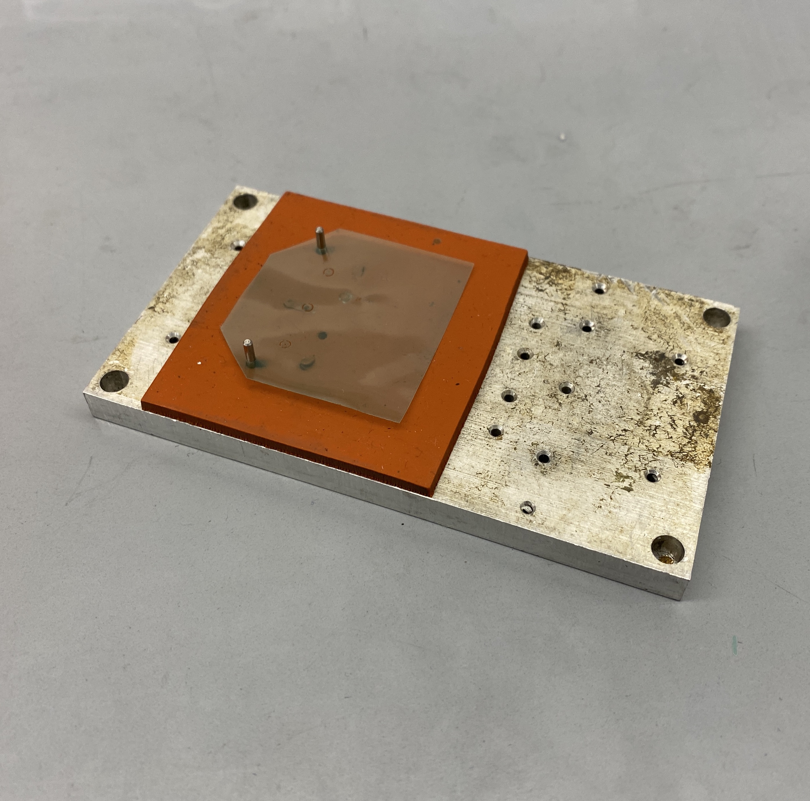
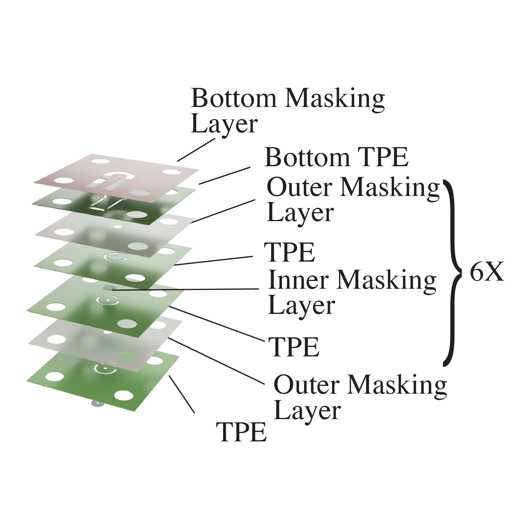
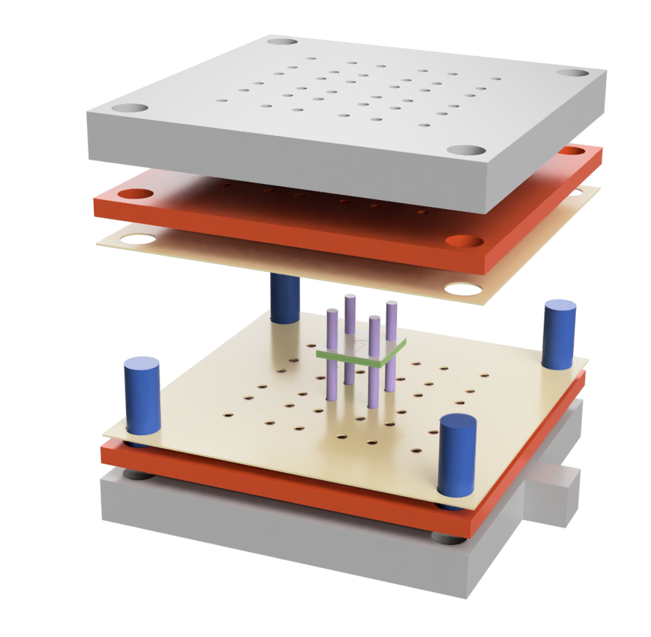
The primary goal was to increase the accuracy and precision of the fabrication process. First, I wanted to redesign the film layers in order to increasse the number of points of constraint from two (Figure 3) to four points (Figure 5). Secondly, with the previous process, each film was designed to allow for fabrication of three bellows at a time. However, at milimeter scale, it was difficult to align the layers with just two points of constraint - tyring to align one bellow would misalign the others. There were many failed bellows with this process. Therefore the updated film design allowed for only one bellow to be aligned at a time (per film sheet).
For the aluminum alignment plate design, I created multiple hole patterns to allow for layering/fabrication of more than one bellow (Figure 5). In the previous fixture, we noticed that the top and bottom alignment plates were difficult to separate after heat/pressure pressing. Therefore, the bottom alignment plate was designed with tabs to help ease in the separation.
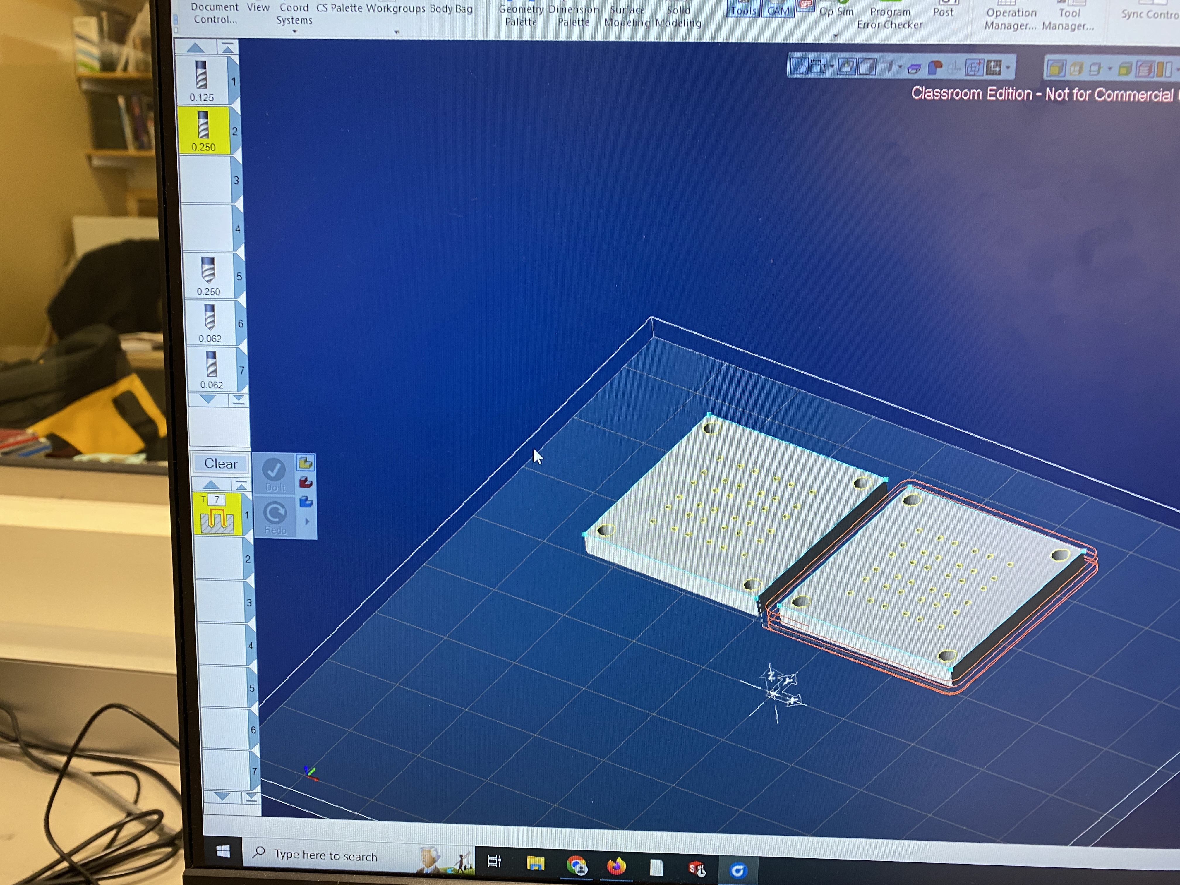
Once the CAD model had been designed, GibbsCAM was used to develop the toolpaths for the CNC Mill (Figure 4).

Figure 3. Old Alignment Plates

Figure 4. GibbsCAM for CNC Milling

