tensile testing fixture

Problem

During tensile testing, the samples can break at the grips - which is not a true measurement of the breaking strength of the material. A new method of securing the sample in the Instron grips must be created to measure the true breaking strength.


Objective

To design a new method of securing the sample in the Instron grips for tensile testing of the sample.

Skills Employed

  • SOLIDWORKS 3D CAD model
  • Technical 2D drawings with tolerances
  • Documentation of fixture according to company’s protocols
  • Testing fixture design/mechanical testing
  • Instron Tensile Testing and Test Method Development
Image of tensile testing fixture
Figure 1. 3D CAD Model of Tensile Testing Fixture for Device
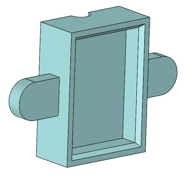
Image of tensile testing fixture
Figure 2. 3D CAD Model of caps that can secure onto the pneumatic grips of the Instron

Approach

After brainstorming and understanding the design requirements, I decided to 3D model a collet chuck fixture to secure the sample. The fixture included two main custom components. The first component was a bushing/mandrel that was designed to act as support for the inside of the sample. The second component is the attachment to the Instron. The custom designed components, the purchased collet and chuck were able to be manufactured into one piece and could be used for testing.

To test this fixture, I was able to run through a few tests with some test samples. After the test runs, I found that it was difficult to find a consistent way to secure the sample using this fixture - either the fixture would be tightened too much and break at the grips (which is the same failure mode that we want to avoid) and not tightening enough will cause the sample to slip from the fixture. After making a design change to the length of the bushing/mandrel, the custom part was sent out to be manufactured - waiting on this custom part to continue testing.

While waiting for this bushing/mandrel, a new design for this fixture was underway. I designed two caps that can secure onto the pneumatic grips of the Instron - waiting on parts for testing of fixture.


Image of tensile testing fixture
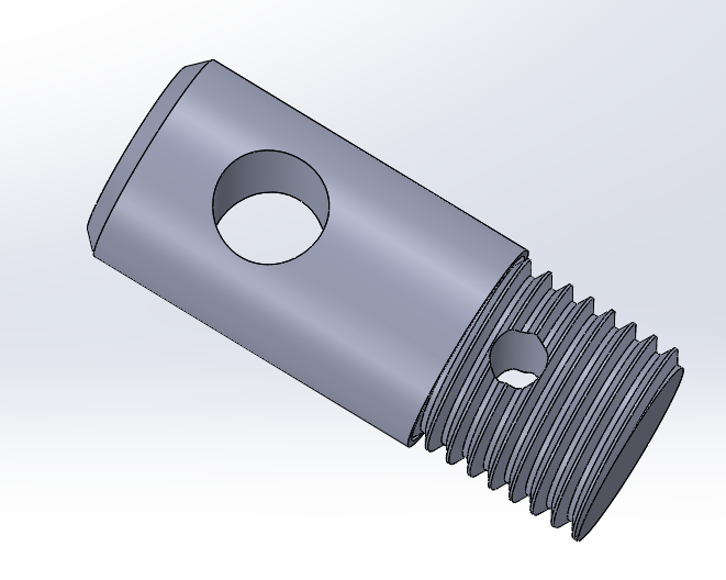
Figure 3. 3D CAD Model of custom Instron to collet chuck adaptor
Image of tensile testing fixture
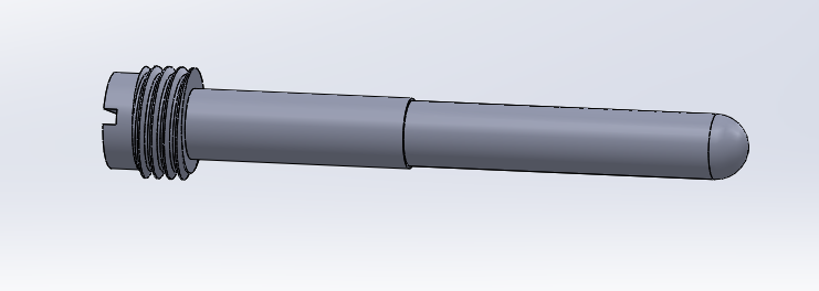
Figure 4. 3D CAD Model of custom device bushing/mandrel to go inside of the collet chuck fixture
Image of tensile testing fixture
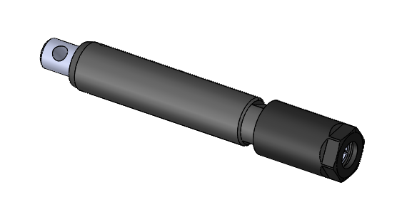
Figure 5. 3D CAD Model Assembly of custom device bushing/mandrel, Instron adaptor, and collet chuck

Results

The fixture could successfully secure the device sample to measure the true failure force and failure break point of the device. Due to proprietary information, the real fixture is unable to be displayed.

Video 1. 3D CAD Model Assembly of custom device bushing/mandrel, Instron adaptor, and collet chuck

to the top
professional
the whole shabang

Copyright © Jen Yeo 2024