mri visual stimulus goggles

Problem

Currently, there isn’t yet a way to provide visual stimuli to both eyes simultaneously and individually to see which side of the brain has stronger results (contralateral vs ipsilateral).


Objective

To design and build visual stimulus goggles for ultra-high field (7 Tesla) MRI for high resolution studies of functional organization of visual cortex using SOLIDWORKS, Arduino, and EAGLE. The goggles must be electromagnetically compatible to a high-res 7T MRI, compact, able to control color, able to adjust luminance, provide motion stimulus, and binocularly adjustable.

Skills Employed

  • SOLIDWORKS 3D CAD model
  • EAGLE: schematics and PCB layouts
  • Arduino
  • Working with electromechanical design in ultra-high field MRI
  • Machine shop manufacturing and tool use (tapping, drills, sanding)
  • Testing fixture design/mechanical testing
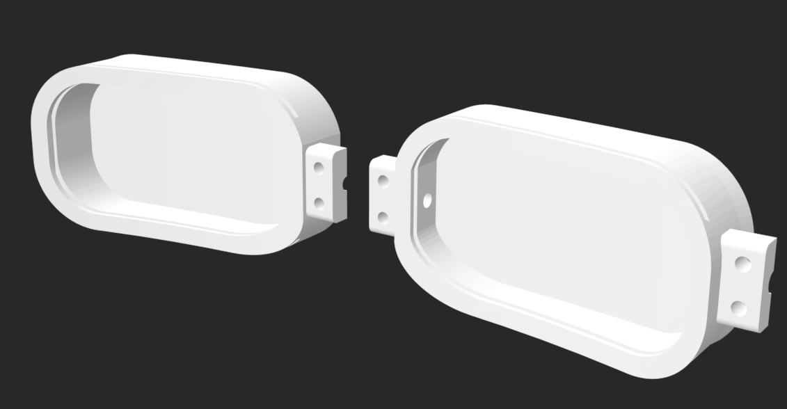
Image of Goggles STL
Figure 1. 3D CAD Model of MRI Visual Stimulus Goggles
Video 1. Working MRI Visual Stimulus Goggles

Approach

After working with my boss on the technical requirements of electronics that are 7T MRI compatible, I started to brainstorm some ideas. Then, I designed the goggle frame using SOLIDWORKS. The goggle frames include strain relief clamps for the wires, as well as a slit for a diffuser. The goggles were curved in a way to help provide full coverage around the patient’s head - cleanable, hygienic padding will be added.

I searched online for compact, non-magnetic LEDs with a voltage and current in our range. After finalizing all of our electrical components, the schematic and PCB board design were made in EAGLE. The PCB board was then sent out to be manufactured.

After receiving the PCB boards from the manufacturer, the next step was to secure the LEDs, inductors, chokes, capacitors, and wires onto the PCB. I initially tried to use a soldering iron, but it proved to be tricky as it was difficult to establish a secure connection between teh PCB and the component and also hard to avoid melting the electrical components. I eventually tried the solder cream and an oven to secure the components properly. I was able to use a multimeter to check for a complete circuit and to troubleshoot any issues that arose. After some troubleshooting, I was able to start testing the goggles with an Arduino code generated by the previous project owner and the first version of these 7T MRI goggles were created!

Image of Goggles STL
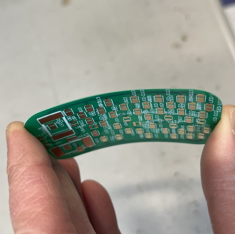
Figure 3. Flexible PCB
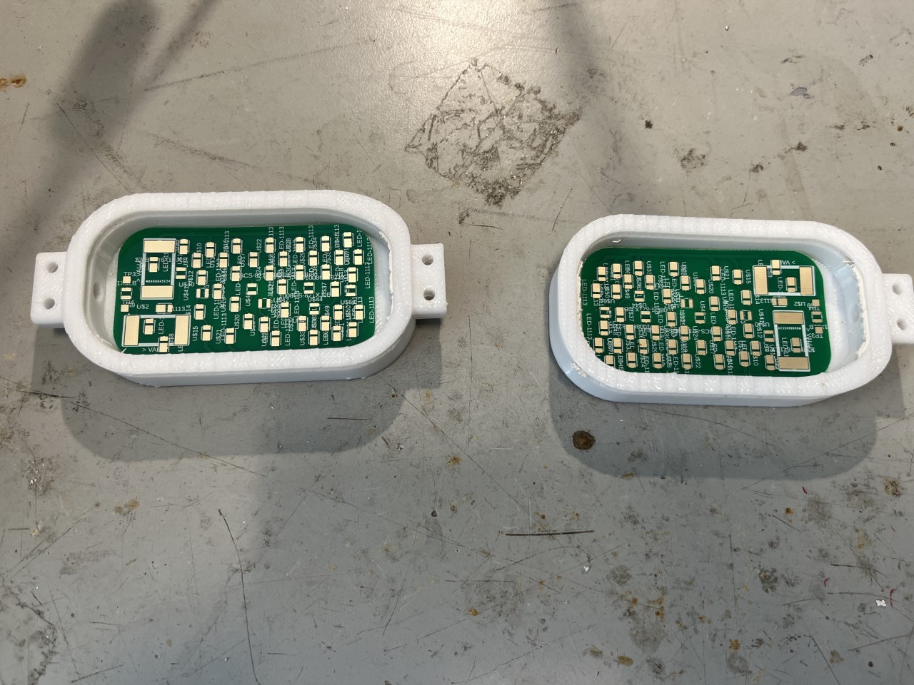
Image of Goggles STL
Figure 4. Flexible PCBs in 3D Printed Goggle Frame; A flexible PCB is used to fit better into the curved goggle frame
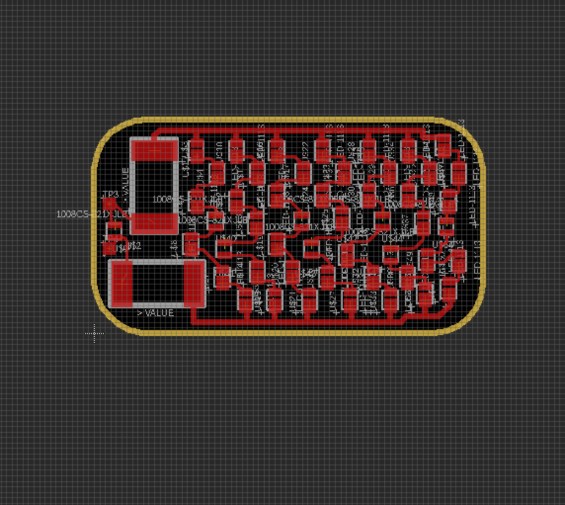
Image of Goggles PCB Layout
Figure 2. Solder Pad Layout of All Electrical Components in EAGLE

Results

The first version of the 7T MRI goggles have been prototyped!

Image of Goggles STL
Figure 5. Top view of MRI Goggles - Diffuser placed for safety of user
Image of Goggles STL
Figure 6. LEDs turned on for the MRI Goggle Prototype
Image of Goggles STL
Figure 7. LEDs turned off for the MRI Goggle Prototype
to the top
research
the whole shabang

Copyright © Jen Yeo 2024