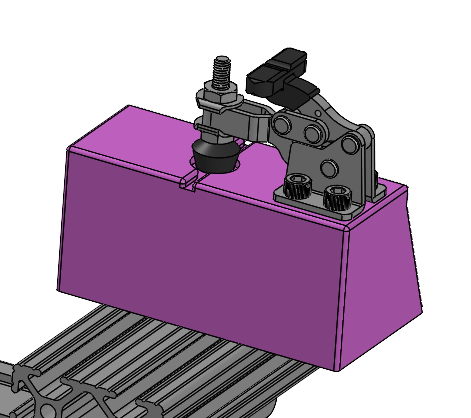
simulated use fixture

Problem

The company’s products required fixtures to stabilize and consistently mobilize each component during actuation and force measurements during a simulated use test.


Objective

To design and build fixtures that can securely hold and smoothly actuate each component during each step of the test.

Skills Employed

  • SOLIDWORKS 3D CAD model and 2D drawings with tolerances
  • 3D Printing FDM
  • Laser Cutting
  • Working with 80-20 rails, linear bearings, structural brackets, fasteners
  • Snap-fits, cavity, and t-slot designs
  • Machine shop manufacturing and tool use (chop saw, tapping, drills, sanding)
  • Working with heat set and press fit inserts, ACME lead screws, thumbs screws, set screws, toggle clamps, micrometers
  • Hand-held force gauge
  • Testing fixture design/mechanical testing
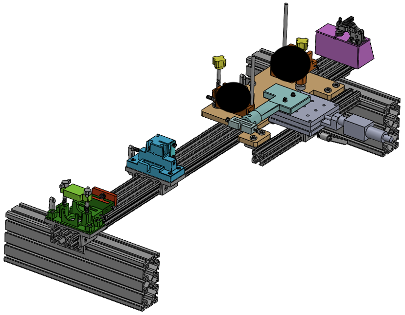
Image of Sim-Use Fixturing CAD
Figure 1. 3D CAD Model of Simulated Use Testing Fixture Assembly

Approach

After reviewing the actions of the sim-use test, I designed various fixtures using SOLIDWORKS.

All moving components were attached to a linear bearing for smooth movement along the 80-20. Additionally, all components have t-slots and adaptors for force gauge measurements.

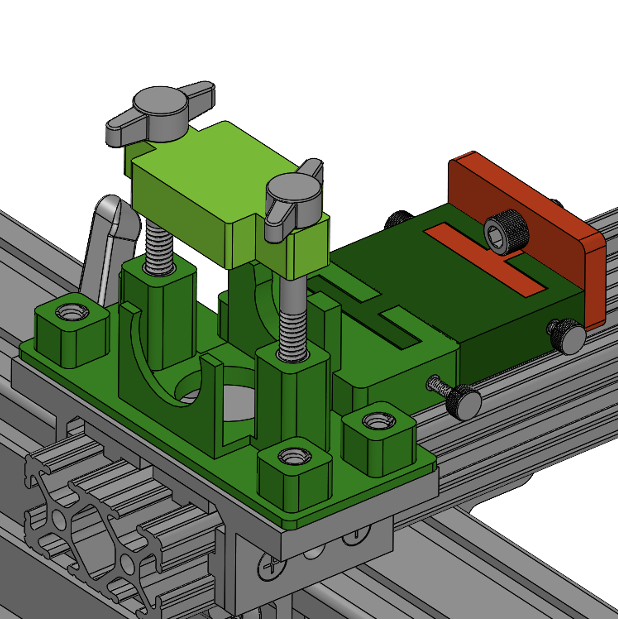
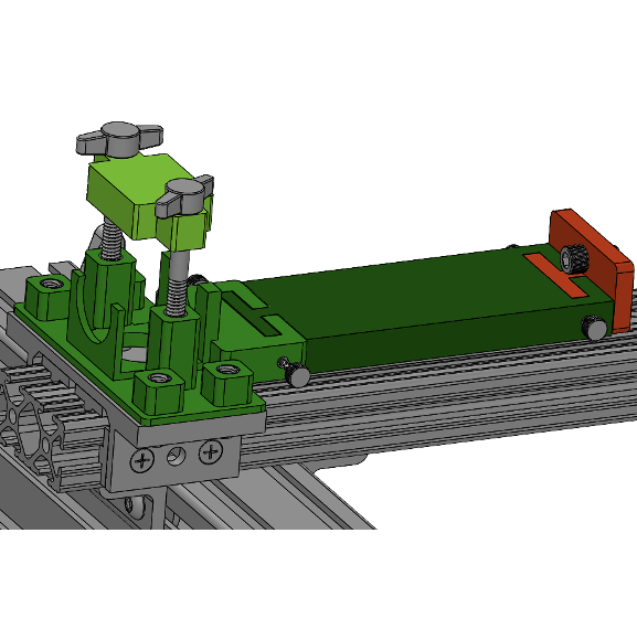
For the first sled, the fixture included two thumb screws (for usability) that would hold a component down, and hold a button down. The first sled component also had snap-fit designs to easily swap components.

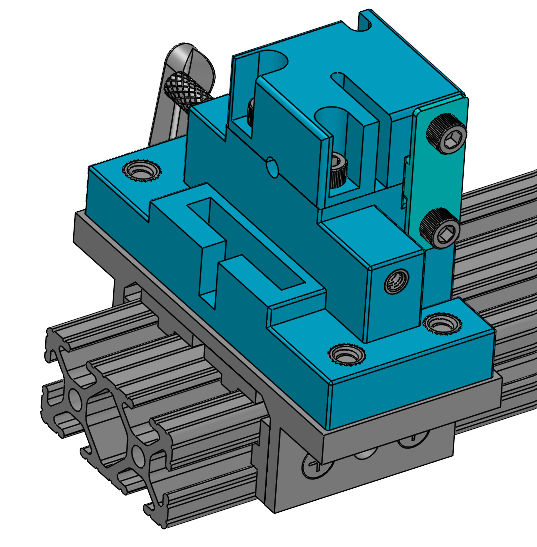
The second sled included a cavity feature in which the product can securely sit inside. The top portion could then be screwed to push down a part on the component. There was also a simple acrylic slab and thumb screws that easily connected Sled 2 and 3 such that they move in conjunction with one another.

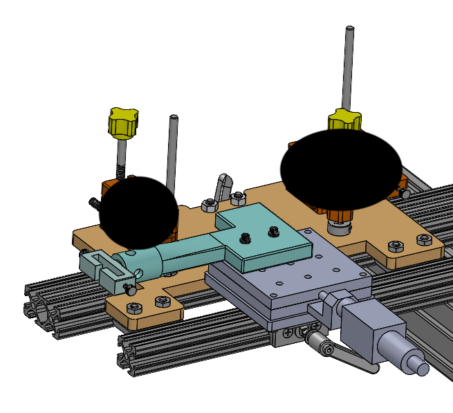
The third, largest, and heaviest sled includes:

  • ACME screws and dowels to move the component in the Z-plane
  • Connecting cap attached to the micrometer to move in the Y-plane
  • Linear bearing to move in the X-plane

Lastly, the wire clamp included a simple toggle clamp to securely hold a guidewire.


Sled 1:

Image of Sim-Use Fixturing CAD
Figure 2. 3D CAD Model of Fixture for Sled 1 - short fixture version
Image of Sim-Use Fixturing CAD
Figure 3. 3D CAD Model of Fixture for Sled 1 - long fixture version

Sled 2:

Image of Sim-Use Fixturing CAD
Figure 4. 3D CAD Model of Fixture for Sled 2 - includes cavity feature inside, t-slot connector, etc

Sled 3:

Image of Sim-Use Fixturing CAD
Figure 5. 3D CAD Model of Fixture for Sled 3 - includes features to move in all 3 translational degrees of freedom.


Wire Clamp

Image of Sim-Use Fixturing CAD
Figure 6. 3D CAD Model of Fixture for Wire Clamp Fixture

Results

The fixtures successfully accomplished its design requirements. They securely held each component and allowed for smooth movement during each actuation of the simulated test runthrough.

Image of Sim-Use Fixturing CAD
Figure 7. Fabricated Sled 1 Fixture - short fixture version
Image of Sim-Use Fixturing CAD
Figure 8. Fabricated Sled 2 Fixture
Image of Sim-Use Fixturing CAD
Figure 9. Fabricated Sled 3 Fixture
Image of Sim-Use Fixturing CAD
Figure 10. Fabricated Wire Clamp Fixture

to the top
professional
the whole shabang

Copyright © Jen Yeo 2024